| Lesson 1:
Getting Started with TinyOS and nesC
Last updated 9 September
2003 |
This lesson introduces the basic concepts of TinyOS and the nesC language in
which the system is written. It includes a quick overview of the nesC language
concepts and syntax to help you get started with programming in this
environment.
The TinyOS system, libraries, and applications are written in nesC, a new
language for programming structured component-based applications. The nesC
language is primarily intended for embedded systems such as sensor networks.
nesC has a C-like syntax, but supports the TinyOS concurrency model, as well as
mechanisms for structuring, naming, and linking together software components
into robust network embedded systems.(不只是一个简单的语言编译器,还包含了一种基于组件和并发的OS模型在里面,直接生成一个含OS的完整系统,有必要对NesC进行进一步的分析了解)
The principal goal is to allow application
designers to build components that can be easily composed into complete,
concurrent systems, and yet perform extensive checking at compile time.
TinyOS defines a number of important concepts that are expressed in nesC:
- First, nesC applications are built out of components with well-defined,
bidirectional interfaces.
- Second, nesC defines a concurrency model, based
on tasks and hardware event handlers, and detects data
races at compile time.(NesC定义了一个基于Task和硬件事件处理的并发模型)
Components
Specification
一个nesC应用包含一个或多个components,它们连接在一起构成一个可执行的应用.
一个component 提供和使用接口. 这些接口是双向的,是访问component的唯一访问点.
interface声明称为commands的interface提供者必须实现的函数集合,同时声明另一个称为events的函数集,该接口的使用者必须实现这些事件处理函数.当一个component调用接口中的commands时,它必须实现该接口的events. 单个component可以use或provide多个interfaces和同一接口的多个实例.
Implementation
nesC中包含两类components:
- modules:提供应用代码,实现一个或多个interface.
- configurations:用来组装其他components到一起, 连接这些components使用的interfaces到其他组件提供的interfaces. 这也称为wiring(连线,类似VHDL中的结构模型). 每个nesC应用通过把内部组建连接起来的top-level configuration进行描述.
nesC对所有源文件使用".nc"扩展名 --
interfaces, modules, and configurations. Please see TinyOS
Coding and Naming Conventions for more information on naming conventions.
Concurrency Model
TinyOS仅执行一个程序,包含运行应用所需的系统组件和定制组件(用户定义编制的). 存在两条执行threads:
- tasks:任务就是函数,其执行是预留的(defered),一旦调度,它们就被执行,直至完成,无法被剥夺.
- hardware
event handlers:硬件中断响应程序,同样运行到完成,但是可以剥夺task和其他hardware event
handler的执行。作为硬件事件处理程序的一部分执行的Commands和events必须用async关键字声明.
因为任务和硬件事件处理程序可以被其他异步(asynchronous)代码占先执行,nesC程序可能会出现某种竞争条件(race conditions). 这可以通过访问任务间互斥的共享数据来避免,也可以通过在atomic语句内完成所有对共享数据的访问. nesC编译器可以在编译时报告潜在的data races,存在误报的可能,这种情况可以使用norace关键字来声明相关变量,但是该关键字的使用要非常慎重.
Please see the nesC Language Reference
Manual for more information on programming in nesC.
| An example application:
Blink |
So far this is all fairly abstract - let's look at a concrete example: the
simple test program "Blink" found in apps/Blink in the TinyOS tree. This application
simply causes the red LED on the mote to turn on and off at 1Hz.
Blink application is composed of two components:
- a module:"BlinkM.nc"
- a configuration:"Blink.nc".
Remember that
all applications require a top-level
configuration file, which is typically named after the application itself. In
this case
Blink.nc is the configuration for the Blink application and
the source file that the nesC compiler uses to generate an executable file.
BlinkM.nc, on the other hand, actually provides the
implementation of the Blink application. As you might guess,
Blink.nc is used to wire the BlinkM.nc module to other
components that the Blink application requires.
The reason for the distinction between modules and configurations is to allow
a system designer to quickly "snap together" applications. For example, a
designer could provide a configuration that simply wires together one or more
modules, none of which she actually designed. Likewise, another developer can
provide a new set of "library" modules that can be used in a range of
applications.
Sometimes (as is the case with Blink and BlinkM) you will
have a configuration and a module that go together. When this is the case, the
convention used in the TinyOS source tree is that Foo.nc represents a
configuration and FooM.nc represents the corresponding module. While
you could name an application's implementation module and associated top-level
configuration anything, to keep things simple we suggest that you adopt this
convention in your own code. There are several other naming conventions used in
TinyOS code; a summary is provided
| The Blink.nc
configuration |
The nesC compiler, ncc, compiles a nesC
application when given the file containing the top-level configuration. Typical
TinyOS applications come with a standard Makefile that allows platform selection
and invokes ncc with appropriate options on the application's top-level
configuration.
Let's look at Blink.nc, the configuration for this application
first:
Blink.nc configuration Blink {
//其中可以说明uses和provides语句,配置可以使用和提供接口
}
implementation { //配置的具体实现
components Main, BlinkM, SingleTimer, LedsC;//本配置涉及到的组件
//下面是连线,类似VHDL语言中的结构模型中信号的连接
//左边的接口(use)绑定到右边的接口实现(provide)
Main.StdControl -> BlinkM.StdControl;
Main.StdControl -> SingleTimer.StdControl;
BlinkM.Timer -> SingleTimer.Timer;
BlinkM.Leds -> LedsC; //相当于BlinkM.Leds -> LedsC.Leds
} |
The first thing to notice is the key word configuration, which
indicates that this is a configuration file. The first two lines,
  configuration Blink {
  }
simply state that this is a
configuration called
Blink.
Within the empty braces here it is possible
to specify uses and provides clauses, as with a module. This
is important to keep in mind:
a configuration can use and provide interfaces!
The actual configuration is implemented within the pair of curly bracket
following key word implementation . The componentsline
specifies the set of components that this configuration references, in this case
Main, BlinkM, SingleTimer, and LedsC. The
remainder of the implementation consists of connecting interfaces used by
components to interfaces provided by others.
Main是TinyOS应用第一个执行的组件.更精确的说,Main.StdControl.init()命令是TinyOS执行的第一个命令,紧跟着是Main.StdControl.start()命令. 因此任何TinyOS应用必须在其顶层配置中包含Main组件。StdControl是一个用于初始化和启动TinyOS组件的公共interface. Let us
have a look at tos/interfaces/StdControl.nc:
StdControl.nc interface StdControl {
command result_t init(); //组件初始化时被调用,可调用多次但必须在start和stop之前
command result_t start();//组件启动,即组件实际第一次执行,可调用多次
command result_t stop(); //停止组件,可调用多次
} |
We see that StdControl defines three commands:
- init():called
when a component is first initialized,init() can be called multiple times, but will never be
called after either start() or stop are called.
- start():called when a component is started,
that is, actually executed for the first time;
- stop():called when
the component is stopped, for example, in order to power off the device that it
is controlling.
Specifically,
the valid call patterns of StdControl are
init*(start | stop)* . All
three of these commands have
"deep" semantics;
calling init() on a
component must make it call init() on all of its subcomponents. The
following 2 lines in Blink configuration
  Main.StdControl -> SingleTimer.StdControl;
  Main.StdControl -> BlinkM.StdControl;
wire
the StdControl interface in Main to the StdControl
interface in both BlinkM and SingleTimer.
SingleTimer.StdControl.init()and
BlinkM.StdControl.init() will
be called by
Main.StdControl.init(). The same rule applies to the
start() and stop() commands.
Concerning used interfaces, it is important to note that subcomponent
initialization functions must be explicitly called by the using component. For
example, the BlinkM module uses the interface Leds, so Leds.init() is called
explicitly in BlinkM.init().
nesC uses arrows to determine relationships between interfaces. Think of the
right arrow (->) as "binds to". The left side of the arrow binds an
interface to an implementation on the right side. In other words, the component
that uses an interface is on the left, and the component provides
the interface is on the right.
The line
BlinkM.Timer -> SingleTimer.Timer;
is used to
wire the
Timer interface used by BlinkM to the Timer interface provided by
SingleTimer. BlinkM.Timer on the left side of the arrow is referring to
the
interface called Timer (
tos/interfaces/Timer.nc), while
SingleTimer.Timer on the right side of the arrow is referring to the
implementation of Timer (
tos/lib/SingleTimer.nc).
Remember that
the arrow always binds interfaces (on the left) to implementations (on the
right).
nesC supports multiple implementations of the same interface. The
Timer interface is such a example. The SingleTimer component
implements a single Timer interface while another component,
TimerC, implements multiple timers using timer id as a parameter.
Further discussions on timers can be found in Lesson 2.
Wirings can also be implicit. For example,
BlinkM.Leds -> LedsC;
is really shorthand for
BlinkM.Leds -> LedsC.Leds;
If no interface name is given on the
right side of the arrow, the nesC compiler by default tries to bind to the same
interface as on the left side of the arrow.
Now let's look at the module BlinkM.nc:
BlinkM.nc module BlinkM {
provides {
interface StdControl;
}
uses {
interface Timer;
interface Leds;
}
}
// Continued below... |
The first part of the code states that this is a module called
BlinkMand declares the interfaces it provides and uses. The
BlinkM module provides the interface
StdControl. This means that BlinkM implements the
StdControl interface. As explained above, this is necessary to get the
Blink component initialized and started. The BlinkM module also uses two
interfaces: Leds and Timer. 这意味着BlinkM可以调用它use的接口中声明的任何command,而且必须实现这些接口中声明的任何events.
The Leds interface defines several commands like
redOn(),redOff(), and so forth, which turn the different LEDs
(red, green, or yellow) on the mote on and off. Because BlinkM uses the
Leds interface, it can invoke any of these commands. Keep in mind,
however, that Leds is just an interface: the implementation is
specified in the Blink.nc configuration file.
Timer.nc is a little more interesting:
Timer.nc interface Timer {
command result_t start(char type, uint32_t interval);
command result_t stop();
event result_t fired();//本接口会触发fired事件,使用者必须实现该事件的响应程序
} |
Here we see that Timer interface defines the start() and
stop() commands, and the fired() event.
The start() command is used to specify the type of the timer and the
interval at which the timer will expire. The unit of the interval argument is
millisecond. The valid types are TIMER_REPEAT and
TIMER_ONE_SHOT. A one-shot timer ends after the specified interval,
while a repeat timer goes on and on until it is stopped by the stop()
command.
How does an application know that its timer has expired? The answer is when
it receives an event. The Timer interface provides an event:
event result_t fired();
An
event is a function that the
implementation of an interface will signal when a certain event takes place. In
this case, the
fired() event is signaled when the specified interval
has passed. This is an example of a
bi-directional interface: interface不仅提供
commands供 接口使用者调用, 同时也会触发
events,这将调用使用者接口中定义的事件处理程序。可以把event当成一个接口实现将调用的回调函数. 使用某个接口的模块必须实现该接口中使用的事件处理程序.
Let's look at the rest of BlinkM.nc to see how this all fits
together:
BlinkM.nc, continued implementation {
command result_t StdControl.init() {
call Leds.init();//显式调用init
return SUCCESS;
}
command result_t StdControl.start() {
return call Timer.start(TIMER_REPEAT, 1000) ;
}
command result_t StdControl.stop() {
return call Timer.stop();
}
event result_t Timer.fired()
{
call Leds.redToggle();
return SUCCESS;
}
} |
This is simple enough. As we see the BlinkM module implements the
StdControl.init(), StdControl.start(), and
StdControl.stop() commands, since it provides the StdControl
interface. It also implements the Timer.fired() event, which is
necessary since BlinkM must implement any event from an interface it
uses.
The init() command in the implemented StdControl interface
simply initializes the Leds subcomponent with the call to Leds.init().
The start() command invokes Timer.start() to create a repeat
timer that expires every 1000 ms. stop() terminates the timer. Each
time Timer.fired() event is triggered, the Leds.redToggle()
toggles the red LED.
You can view a graphical representation of the component relationships within
an application. TinyOS source files include metadata within comment blocks that
ncc, the nesC compiler, uses to automatically generate html-formatted
documentation. To generate the documentation, type make <platform>
docs from the application directory. The resulting documentation is located
in
docs/nesdoc/<platform>.docs/nesdoc/<platform>/index.html
is the main index to all documented applications.
| Compiling the Blink
application |
TinyOS supports multiple platforms. Each platform has its own directory in
the tos/platform directory. In this tutorial,
we will use the mica platform as an example. If you are in the TinyOS source
tree, compiling the Blink application for the Mica mote is as simple as
typing
make mica
in the
apps/Blink
directory. Of course this doesn't tell you anything about how the nesC compiler
is invoked.
nesC itself is invoked using the ncc
command which is based on gcc. For example, you can type
ncc -o main.exe -target=mica Blink.nc
to compile the
Blink
application (from the
Blink.nc top-level configuration) to
main.exe, an executable file for the Mica mote. Before you can upload
the code to the mote, you use
avr-objcopy --output-target=srec main.exe main.srec
to produce
main.srec, which essentially represents
the binary main.exe
file in a text format that can be used for programming the mote. You then use
another tool (such as
uisp) to actually upload the code to the mote,
depending on your environment. In general you will never need to invoke
ncc or
avr-objcopy by hand, the Makefile does all this for
you, but it's nice to see that all you need to compile a nesC application is to
run
ncc on the top-level configuration file for your application.
ncc takes care of locating and compiling all of the different
components required by your application, linking them together, and ensuring
that all of the component wiring matches up.
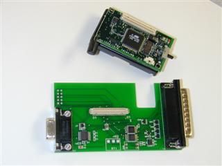
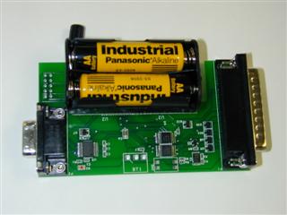
| Programming the mote and
running Blink |
Now that we've compiled the application it's time to program the mote and run
it. This example will use the Mica mote and the parallel-port-based programming
board (mib500). Instructions on how
to use the other programming boards are here. To
download your program onto the mote, place the mote board (or mote and sensor
stack) into the bay on the programming board, as shown below. You can either
supply a 3 volt supply to the connector on the programming board or power the
node directly. The red LED (labeled D2) on the programming board will be on when
power is supplied. If you are using batteries to power the mote, be sure the
mote is switched on (the power switch should be towards the connector).
Plug the 32-pin connector into the parallel port of a computer configured
with the TinyOS tools, using a standard DB32 parallel port cable.
Type: make mica install. If you get the error:
  uisp -dprog=dapa --erase
  pulse
  An error has occurred during the AVR initialization.
   * Target status:
      Vendor Code = 0xff, Part Family = 0xff, Part Number = 0xff

  Probably the wiring is incorrect or target might be `damaged'.
  make: *** [install] Error 2
check
whether the power is on. You can also get this error message if the mote is low
on batteries (if you are using batteries), or if the wrong version of the
uisp programming utility is installed (be sure to use the version in
the TinyOS distribution).
If you are using an IBM ThinkPad, it may be necessary to tell the tools to
use a different parallel port. You can do this by adding the line
PROGRAMMER_EXTRA_FLAGS = -dlpt=3
to the
apps/Makelocal file
(create it if it doesn't exist). The
Makelocal file is for user-specific
Makefile configuration.
If the installation is successful you should see something like the
following:
  compiling Blink to a mica binary
  ncc -board=micasb -o build/mica/main.exe -Os -target=mica  -Wall -Wshadow -DDEF_TOS_AM_GROUP=0x7d -finline-limit=200 -fnesc-cfile=build/mica/app.c  Blink.nc -lm
  avr-objcopy --output-target=srec build/mica/main.exe
  build/mica/main.srec
      compiled Blink to build/mica/main.srec
      installing mica binary
  uisp -dprog=dapa  --erase
  pulse
  Atmel AVR ATmega128 is found.
  Erasing device ...
  pulse
  Reinitializing device
  Atmel AVR ATmega128 is found.
  sleep 1
  uisp -dprog=dapa  --upload if=build/mica/main.srec
  pulse
  Atmel AVR ATmega128 is found.
  Uploading: flash
  sleep 1
  uisp -dprog=dapa  --verify if=build/mica/main.srec
  pulse
  Atmel AVR ATmega128 is found.
  Verifying: flash
You
can now test the program by unplugging the mote from the programming board and
turning on the power switch (if it's not already on). With any luck the red LED
should light up every second - congratulations!
Typing make clean in the Blink directory will clean up the
compiled binary files.
If you are still having errors, then you need to check your TinyOS
installation and check the Mica hardware. See System and
Hardware Verification for details.
To test your new-found TinyOS programming skills, try out the following:
- Modify Blink to display the lower three bits of a counter in the
LEDs.
This tutorial has just scratched the surface of nesC's syntax and features.
Rather than document everything extensively, we refer the reader to the nesC Project Pages as well
as the documentation included with the nesC distribution in nesc/doc.
These sources contain more complete documentation on the language.
Hopefully this should be enough of a start to get you going on programming in
this fun new language.
posted on 2005-11-28 00:54
井冈山 阅读(2089)
评论(0) 编辑 收藏 引用 所属分类:
tinyOS